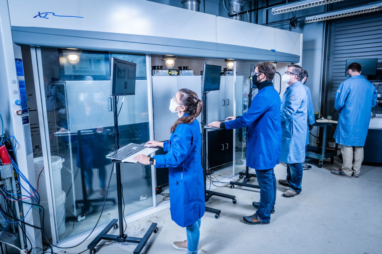

Workup & Isolation Modules
Following the successful Pharmacy on Demand (Pod) Demonstration Campaign, the objective of this project was to design and construct new systems and processes for the continuous synthesis, isolation, formulation, purification, and tableting of a single Active Pharmaceutical Ingredient (API): Ciprofloxacin Hydrochloride.
Eagle Lake was once again tasked with automating the downstream process, building on our experience in the demonstration campaign. To produce the Ciprofloxacin HCl API in the dosage amounts required, and with the requisite purity, two new downstream systems would be required: a Work-up system to purify the Ciprofloxacin crude; and an Isolation system for final purification prior to tableting.
Our client conducted experiments to define the processing steps to be divided between the two systems, and to select the appropriate precipitation agents, wash solvents, and the most effective clean-in-place (CIP) solvents necessary to maximize yield and purity.
The two newly designed systems are substantially similar in electromechanical design and construction.
The software architecture shares the same Model-View-Controller (MVC) framework developed for the demo campaign. System IO for each system is configured and customized using JSON settings files, which allows the software and executables to be almost identical. Recipes for both systems have similar structure and timing.
Given the requirement to build two downstream systems instead of one, system build and assembly was identified as the project’s critical path.
In the demonstration system, hundreds of discrete analog and digital input/output (IO) signals were used to monitor and control the system hardware. The custom Field Programmable Gate Array (FPGA) implementation designed for the demo cRIO controller enables each of the 96 individual digital IO lines to be configured independently as:
- Pulse-Width-Modulation (Stirring Motors, Fans)
- Pulse-Frequency-Modulation (Liquid Pumps)
- Discrete binary (Valves, actuators)
Additional signal conditioning is required to interface between the FPGA’s +3.3V logic and the +24V hardware.
While this “mass of neat spaghetti” wiring approach worked great, it was time-consuming to build, and when in operation, there is no feedback from the devices to indicate that they are operating as desired when driven by the FPGA.
To address these limitations, the hardware design team collaborated closely with Eagle Lake to simplify the implementation, reduce assembly and wiring time, and incorporate new features to enhance system reliability.
For the discrete IO, we leveraged the simplicity of NI’s Remote IO modules. A single EtherCAT network cable connects the Remote IO bus coupler with the cRIO chassis.
Digital modules utilize industrial +24V signals, so valves, coolant pumps and air pumps connect directly to the DIN rail screw terminals. In our MVC implementation, since the Remote IO digital IO uses the scan interface, no additional programming was required.
Analog signal conditioning is integrated into the Remote IO modules, enabling thermocouples to connect directly to temperature input modules, and the pH sensor connects directly to an analog input module. In our MVC implementation, we modified our existing analog input device abstraction to support the unique Remote IO AI scaling, with minimal additional code to integrate with the rest of the MVC.
For the motors and pumps, we harnessed the capabilities of the CANopen protocol using NI’s C Series High-Speed CAN Interface module. A single CANbus cable connects to the module, allowing it to be daisy-chained to each CANbus drive.
CANopen support required constructing a completely new CANbus device abstraction to integrate with the MVC hardware abstraction layer. Using the CANopen protocol, our newly developed device abstraction interfaced with both servo and stepper motor controllers from different manufacturers.
CANbus control of liquid pumps included not just setting an enable and flow rate as we did with PFM, but now included read back of actual flow rate, volume delivered, state, status, and faults.
CANbus control of stirring motors included not just setting enable, speed, and direction as we did with PWM, but now included read back of actual velocity, position, torque, state, status, and faults.
Motors could be operated in velocity mode to stir the solution at a predetermined speed and direction. Alternatively, they could be configured to operate in position mode, and set up to oscillate a predetermined number of revolutions in either direction at a controlled velocity.
The MVC MODEL includes new serial instruments in the device abstraction layer, like scales, flow sensors, and temperature controllers for additional feedback and automated control of operating parameters using new process variables in the data abstraction layer.
For the MVC VIEW, new HMIs were created for each system, employing similar custom controls and indicators derived from the demo system. Motor and Pump UI elements map to the data layer, so nothing new in the UI was required when switching to CANbus motors and pumps, aside from the addition of indicators for actual velocity and status.
For the MVC CONTROLLER, the chemists used the same recipe editor and recipe sequencer employed previously for both systems.
Once the systems were operational, they were delivered to another university research team, which was tasked with evaluating the end-to-end process. This evaluation encompassed identifying and mitigating impurities, scaling up the systems for extended durations, and defining a robust process for producing high-quality APIs.
The final process running on the delivered systems operates continuously and autonomously, resulting in a fourfold increase in throughput while ensuring API purity that meets or surpasses the drug substance specifications.


